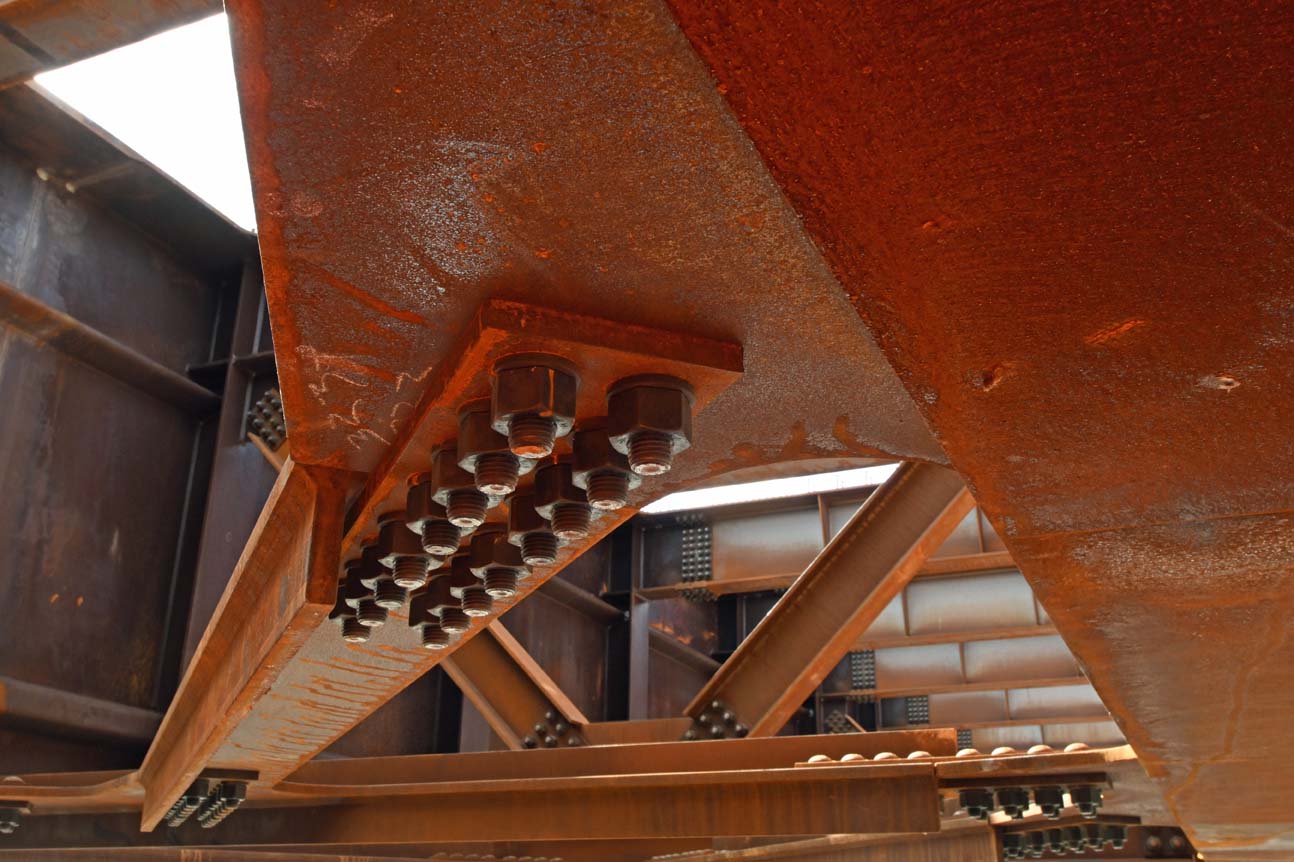
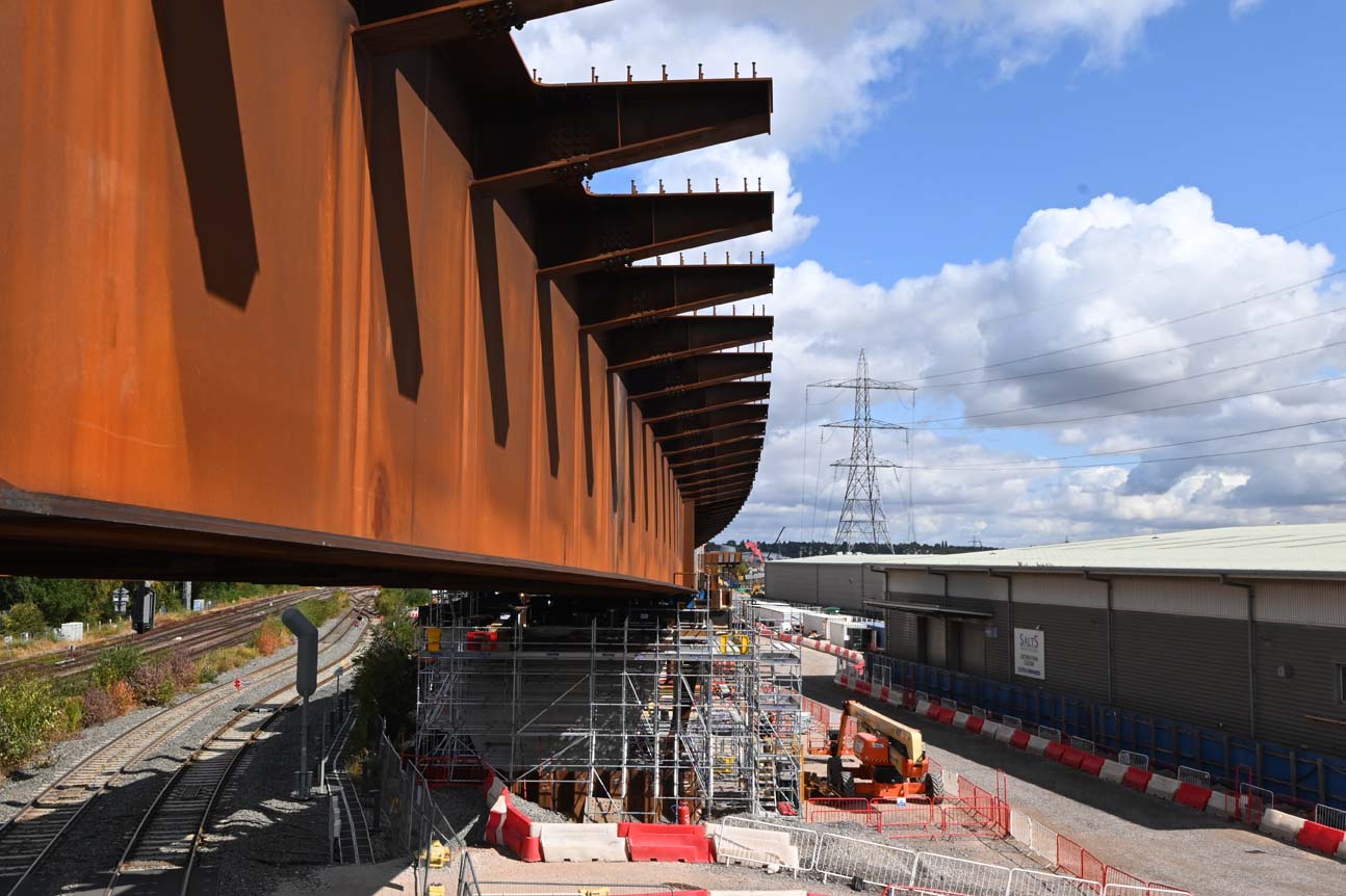
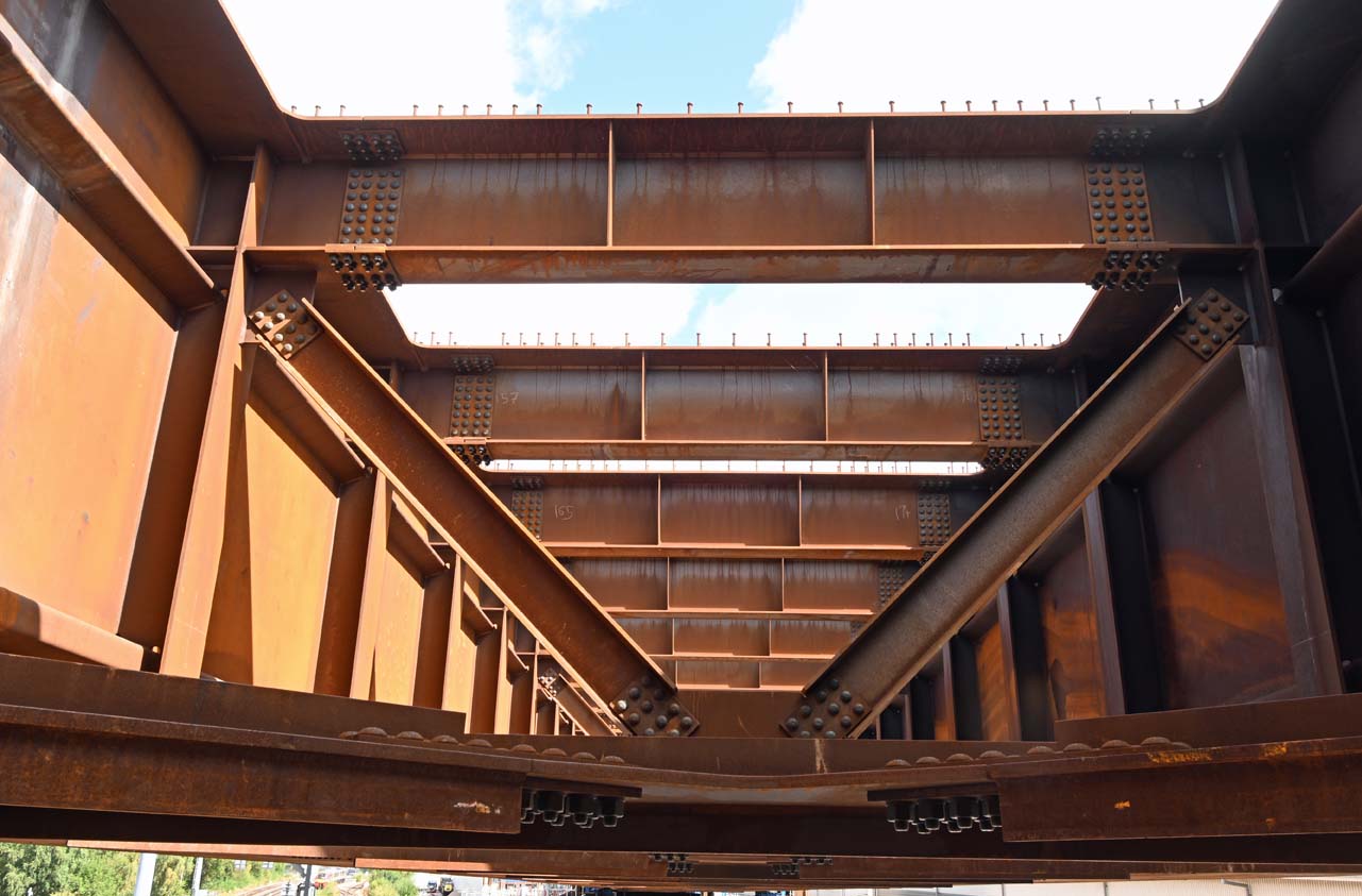
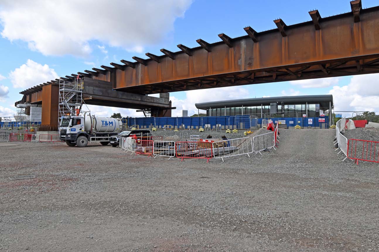
On Wednesday I was privileged to be invited to see the construction of HS2s Duddeston Jn viaduct up close. It’s an impressive structure that’s being built on a very constricted site. To add to the fun the engineering challenge is made tougher by the viaduct’s changing horizontal curve and 3% gradient, which sees it climb to around 12m above the existing railway.
Built by consortia BBV, the weathering steel structure is made up of 14 spans of around 55m apiece. It’ll weigh up to 6,835 tonnes when complete. Seven spans are being built and pushed out over the existing railway lines whilst the remaining seven spans will be built and craned into place to create a 700m long structure.
Duddeston Junction Viaduct is supported by one abutment, two steel piers, four portals and eight concrete piers. It’s the longest viaduct on the Curzon Approaches by over 400 metres – eclipsing Curzon 1 which measures around 300 metres.
Here’s a selection of pictures from my visit.
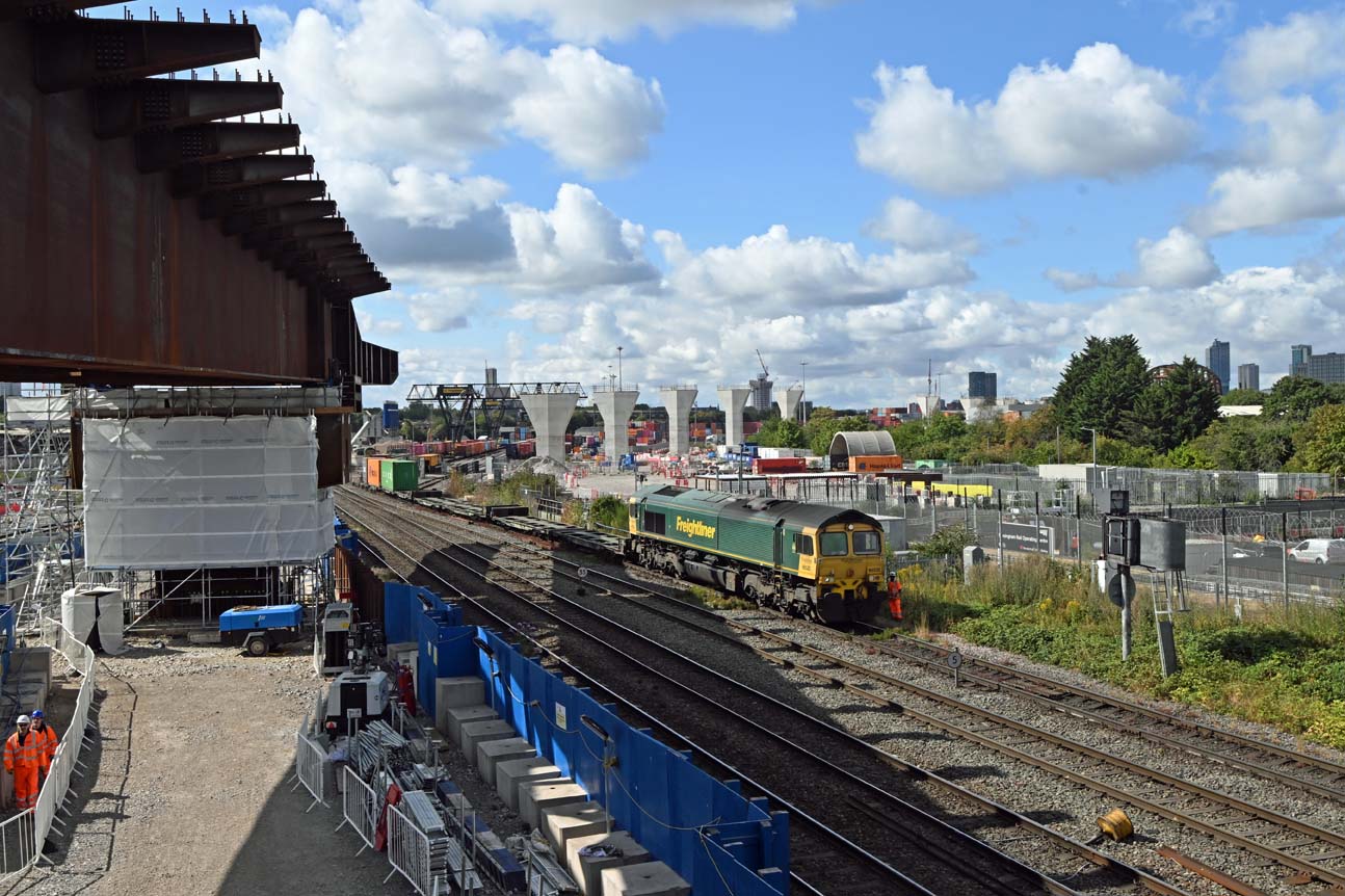
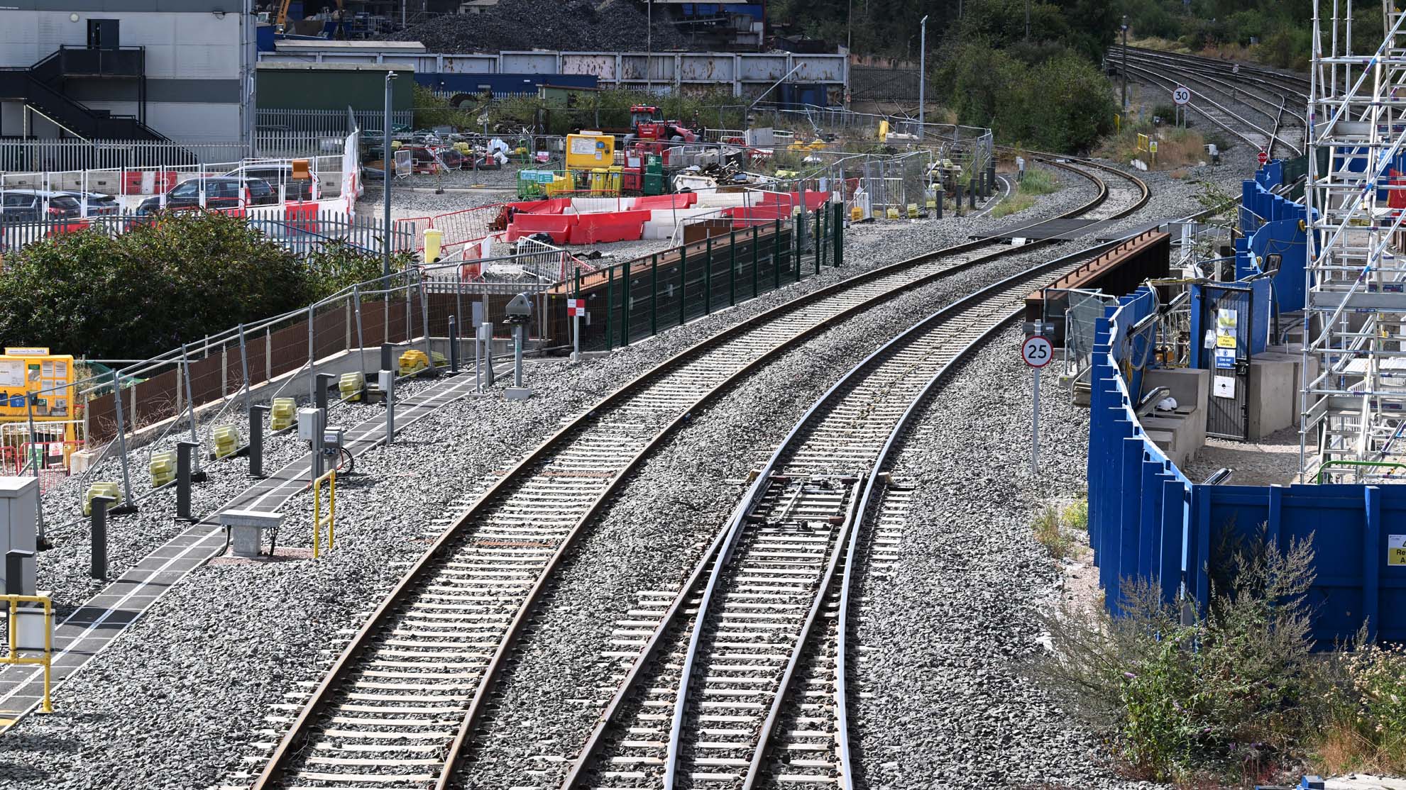
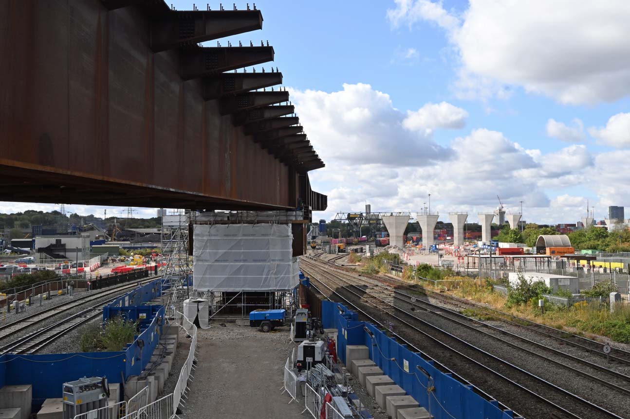
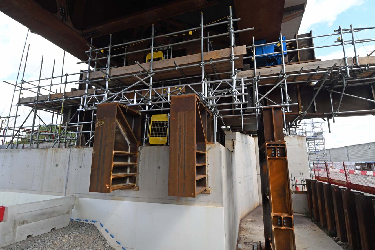
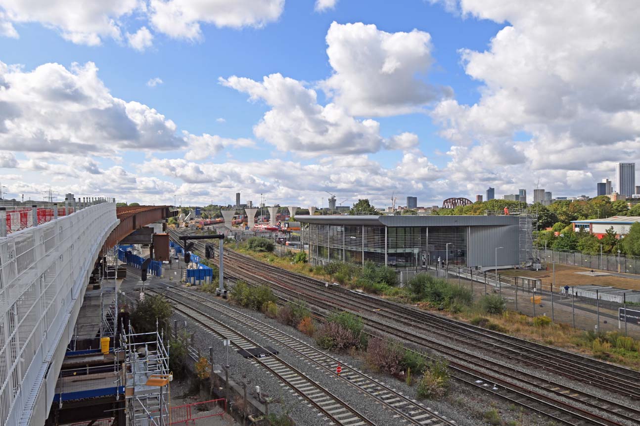
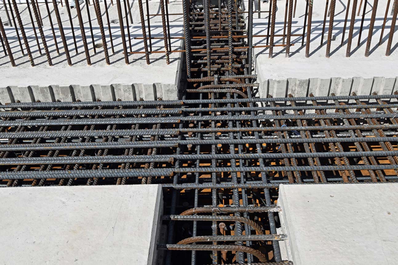
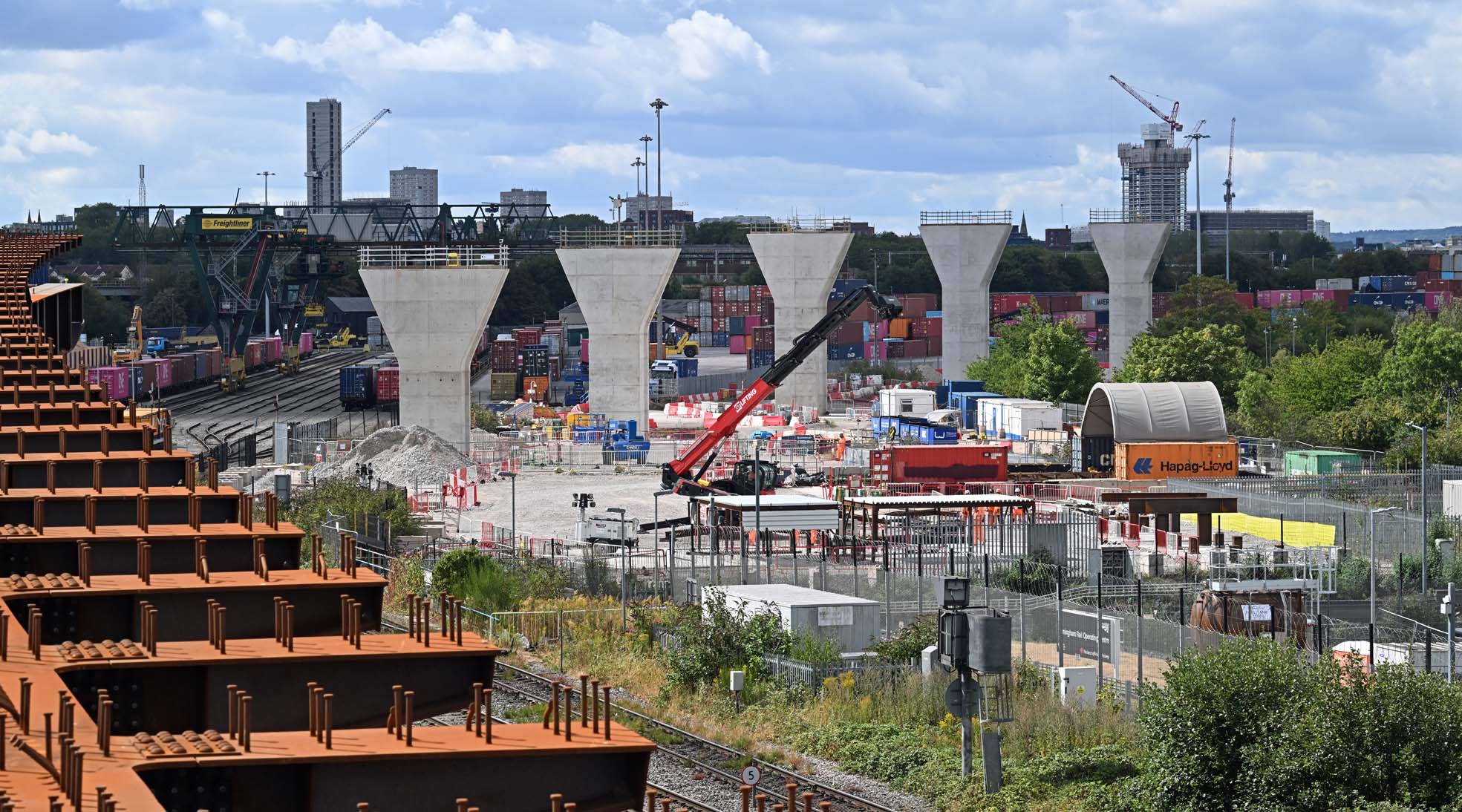
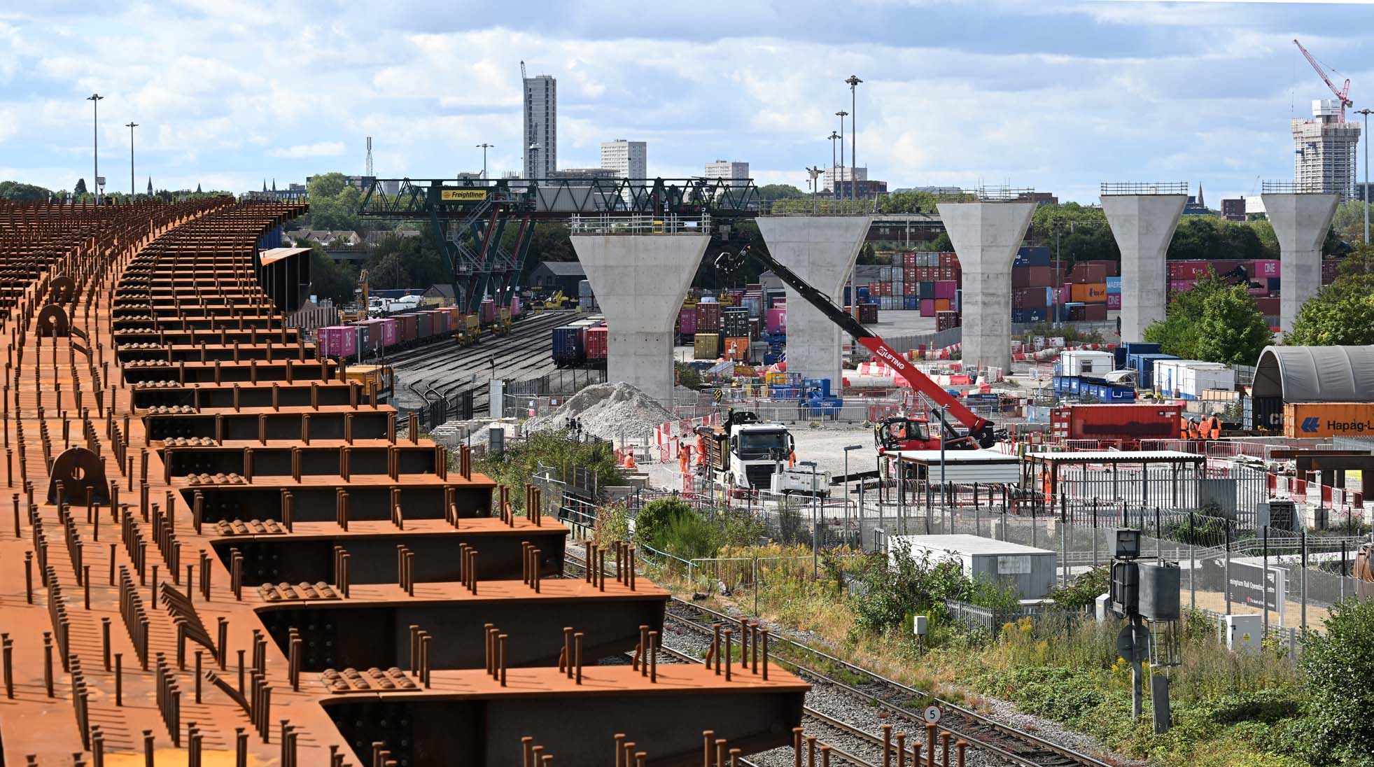
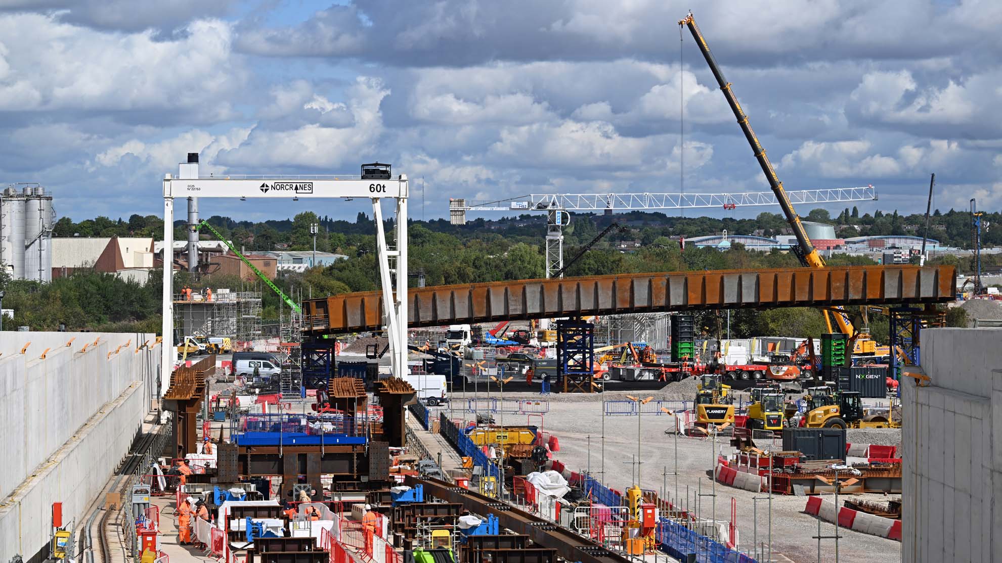
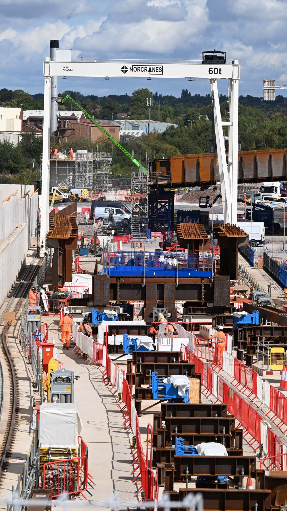
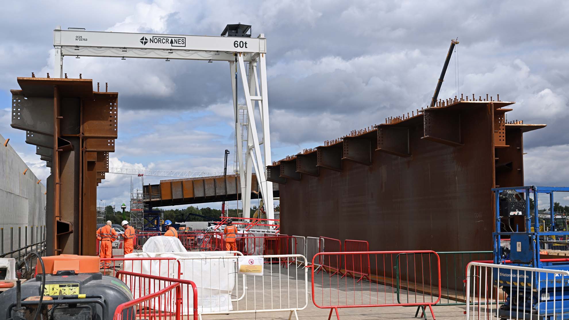
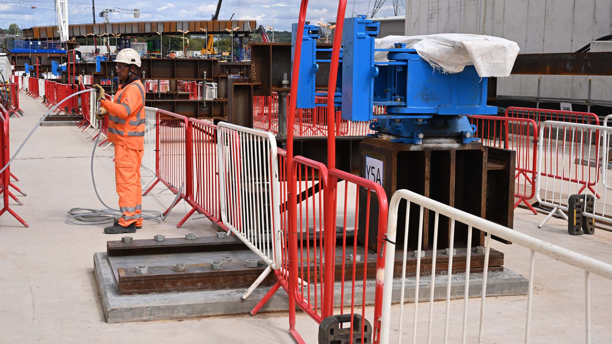
A freightliner Class 66 passes where the viaduct will be pushed out over the four tracks of the busy Birmingham to Derby main line. In the background is the Freightliner container terminal whilst the pillars of the HS2 line lead your eye towards the Curzon St No2 viaduct which can be seen peeping out from behind the trees. These two freight lines are new. The originals had to be slewed to provide a space for one of the HS2 viaduct pillars. This involved building a new bridge over Duddeston Mill Rd which can be seen in the picture. The diverted freight lines are to the left of this pillar, which was built on the course of the original formation. The 20m wide gap that was created allowed the bridge pillar to be built. The viaduct is like one giant Meccano set, with the weathered steel being welded (or bolted) together on site. Looking along the viaduct towards Washwood Heath. The constricted nature of the site is evident. HS2 have taken over the warehouse to the right which is used for offices and storage. The weathered steel that makes up the viaduct is shipped in from Portugal, then put together on site. That white line? That’s where two sections have been welded together. Looking along the inside of the viaduct. Unlike other HS2 viaducts at Wendover and elsewhere, this one will be left open at the bottom. The viaduct with Birmingham ROC (Rail Operating Centre) in the background. You can see where sections have been welded together. To the left is the ‘nose’ of the viaduct, which is the guide fitted to it whilst it’s pushed out. The pile cap and wing walls which form the start of the viaduct. This is a massive structure sitting in piles of 1.8 meters in diameter sunk to 20 meters in depth. It’s designed to take the stresses of high speed trains passing over the viaduct.. Looking along the viaduct towards central Birmingham, with the ROC to the right and Curzon St No2 viaduct on the horizon beyond. Building the bridge deck insitu. The size and complexity of the rebar is evident. The bridge deck waiting for the next section to be built so that it can be pushed out further. The curvature is evident. Pillars for the viaduct on the opposite side of the existing railway. One the viaduct is pushed out to bridge the railway the remaining seven spans of the viaduct that will bridge these pillars will be built on site and lifted into place. A telephoto view that gives an impression of the curvature of the viaduct.The back of the viaduct with sections of it being assembled before being joined to the existing structure. The constrained nature of the site is evident. Part of the problem in building the viaduct is the curvature, which means the length of sections that can be built at any one time is limited. In the background is the first of four spans of the new Washwood Heath viaduct, a replacement road bridge. This span will be lifted into place over the railway during a blockade over the August bank holiday. The assembly area for viaduct sections with the gantry crane used for lifting them into position. The steel is brought in by road, which presents its own logistical challenges due to the size and weight of some of the pieces. Sections of the weathered steel in the assembly area. One of the bearings that the viaduct is slid over. This one is capable of being moved to left or right, hence the long pad it’s sat on. Who says no rails have been laid on HS2 yet? OK, admittedly, this is only for the travelling crane!
I’ve a small favour to ask… If you enjoy reading this or any of the other blogs I’ve written, please click on an advert or two. You don’t have to buy anything you don’t want to of course – although if you did find something that tickled your fancy that would be fab! – but the revenue from them helps me to cover some of the cost of maintaining this site (which isn’t cheap and comes out of my own pocket). Remember, 99% of the pictures used in my blogs can be purchased as prints from my other website – https://paulbigland.zenfolio.com/